|
Here is the fifth article
about my F-4S Phantom Odyssey. Today I will focus on making custom photo-etched
parts, as requested by many readers. The article is quite extensive,
and includes 36 photos.
|
The
orientation diagram from my Plane Captain Handbook shows the vent I will
discuss in this article. The part is located on each side of the
aircraft, above the exhaust nozzles. It evacuates bleed air, which enters
the plane in front of the engines, runs along the spine below the
center fuel tanks and keeps the JP-4 at a reasonable temperature. On
the diagram, it is referenced as part no 15 "Fuel Tank Cooling Air
Vent".
|
|
Click on image
below to see larger image |
 | |
|
Click on image
below to see larger image |
 | |
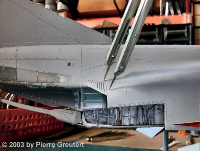
This is
the starting point on the right side. The original Tamiya mold features a
raised vent, which is wrong in shape and size. It definitely needs some
home surgery. |
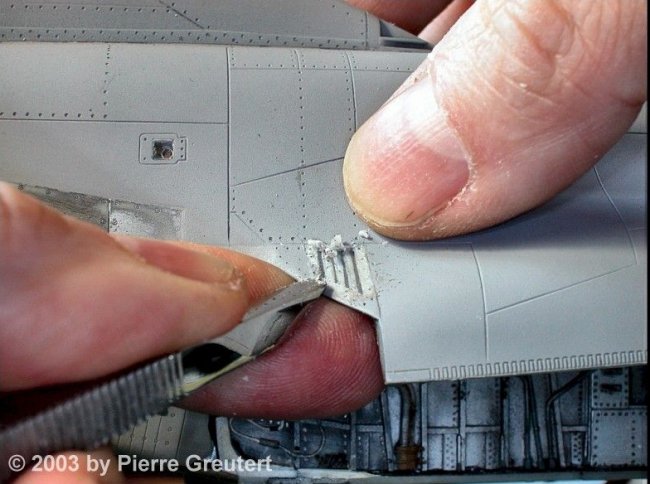
A divider comes in handy, to report the
correct size from the other side, where I already did the correction. Removing
the excess plastic is best achieved with a sharp chisel.
|
Click on images
below to see larger images |
 |
 |
The lower angle is wrong
too. I mark the plastic to be removed, and my Dremel cuts away a
large chunk of plastic.
|
Click on images
below to see larger images |
|

|
 |
The photo-etch session
can now actually begin. As a first step I draw a positive of the parts I
want. Any 2-D CAD program will be OK, mine is GraphicWorks from Micro
Application (www.microapp.com). I design the parts at
4 times the actual size, and let the printer reduce them accordingly. It is an
empiric iterative process: measure on the model, print a paper draft, check,
correct, etc. At the very end, a positive image is printed, like the one shown
here: "Bleed Air Vents".
|
Click on images
below to see larger images |
 |
 |
The final print is on
a transparent ink-jet film. I got mine at Mega Electronics
(www.megauk.com), part no 100-071. I print a copy for the front side, plus a copy
for the back side. A lightbox allows to spot the small dots where the ink is
missing: they must be blackened with a black overhead pen. Finally my sandwich
is assembled, and hold together with cellotape: front drawing - brass sheet
- back drawing.
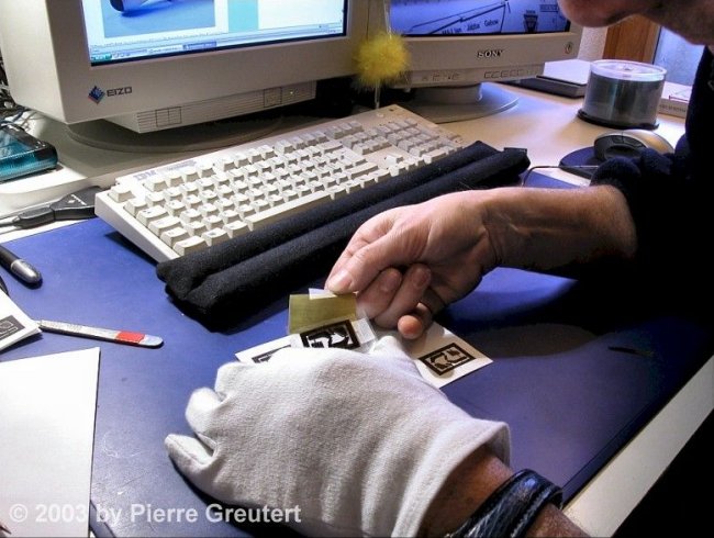
Here comes an important step
in the etching process: the brass sheet must be absolutely clean: no
fingerprints, no grease, no lacquer, nothing but brass. I insist on this point:
wear cotton gloves, and once the sheet is scrubbed, DON'T TOUCH IT ANYMORE with
unprotected fingers. I use a polishing block from Mega Electronics (www.megauk.com), part no 900-009 (I have no personal interest in this company, they
just have a good range of products). Dust off any particle, and once again: keep
away your greasy paws! In this example, I use 005 brass from K&S (0.12mm),
bought at Micro-Mark (www.micromark.com).
The photoresist coating is next. I
use the Seno Applicator positive resist, from Mega Electronics (got it?),
part no SN100. It comes in a black plastic container, with an applicator sponge.
The stuff stinks awfully :-( Since the sponge applicator does not work well on
small brass items, I prefer to open the container and pour its content into a
shallow cup for dipping. This method is the best way to produce a smooth coat.
Make a short dip, let the excess run off one of the corners, and place the wet
sheet as indicated under a cup to protect it from dust. Let it dry in a
pre-heated oven, for 25 minutes at 70°C
Once the coated brass sheet has
cooled down, I insert it between the two film positives, and attach it with
cellotape, so it won't move while I manipulate it. The exposure to UV light is done in a special lightbox. The box
stems from Mega Electronics (sorry: again), part no LV202-E. Alternatively,
you may expose in the bright sun too, but timing is very inaccurate, and
for sure it will be raining outside every time you want to do an exposure. So I
took the plunge and ordered the lightbox, which I can operate anytime. I found
out that 2.5 minutes for each side is a good exposure. How does it work? The UVs impress the unshielded
photoresist,
and a short (20s) dip in a developer solution (Mega Electronics, part no SN111)
dissolves the exposed photoresist, unveiling the positive image of the parts to
be etched.
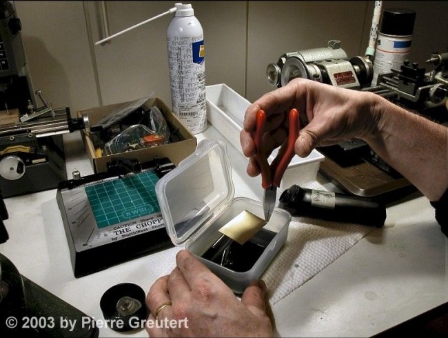
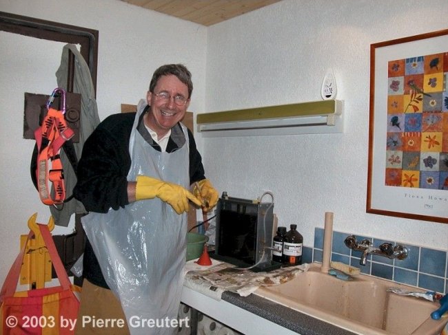
Trimming away the excess brass
around the frame is best done with scissors. The etching now really starts. This is my etch tank, purchased
from Conrad (www.conrad.ch, part number
unknown). Any similar item will be ok, as long as it features the same
specifications: a 1 liter tank, a heating system, and an air bubble generator at
the bottom. The chemical is ferric chloride (FeCl3), 250 grams for 600
milliliters of water. Ferric chloride is an awful product, as it will stain
everything. It is a nasty corrosive chemical - so wear gloves and treat the
stuff with respect. Preheat the solution at about 45-50°C.
The brass sheet is attached to the
tank's holders, and dipped into the bubbling hot etchant. After a couple of
seconds, remove the part to check that everything is fine. You can already see
how the etchant already attacks the exposed brass, leaving the coated areas
untouched. Stick it back into the etchant and start the stopwatch. Check
every now and then. The etch processing time depends on heat, thickness
and saturation of the etchant. Etched brass will slowly saturate the
FeCl3 solution, so etching times get longer. At about 7 minutes (10 or
more with an old solution), you can see how the brass is progressively
etched away. Remove the brass sheet when all parts have been eaten away and
rinse thoroughly under fresh tap water. This stops the etch
process.
Well, the etching is almost
finished, and everything went well. The Scale PhantomPhixer is happy! Time now to strip away the photoresist that
protected the parts. Isopropyl alcohol is fine for the job. The piece is
now somewhat dull, so a last bath in a solution of vinegar + salt
turns it into a shining beauty.
Et voilà! You might wonder how I
engraved the text on the border? Remember that the etching fluid will eat brass
from both sides. Since the text is only printed on the top transparent - not on
the back - the etch will be only half way through when areas which are
transparent on both sides are fully through. This is the way to etch
folding lines, engraved or embossed panels, rivets, etc
How did I start? I learned all
the basics at www.prototrains.com
I can only recommend
you visit this site.
Here is the vent, cut
away from the brass sheet. The vent area on the fuselage gets a coat
of filler to mask the mishaps. I fold the vent
blinds, by twisting delicately each blind with a surgeon scalpel. The filler can dry during this time, and it is now
ready to be sanded smooth. In the middle
of the vent area, I want to make some room for the blinds, and to simulate the
exit duct.
A short grinding session
with the Dremel (no need to be accurate: the well will be a dark pit). The
surgery results in a couple of misaligned panel lines, so I correct this: fill, sand, mask the line with
Dymo tape (it serves as a guide for the scriber), and scribe fine panel lines.
At the end, I airbrush a coat of Model Masters Metalizer (magnesium),
and a couple of minutes later a subtle buff gives the shiny metallic
appearance.
|
Click on image
below to see larger image |
 | |
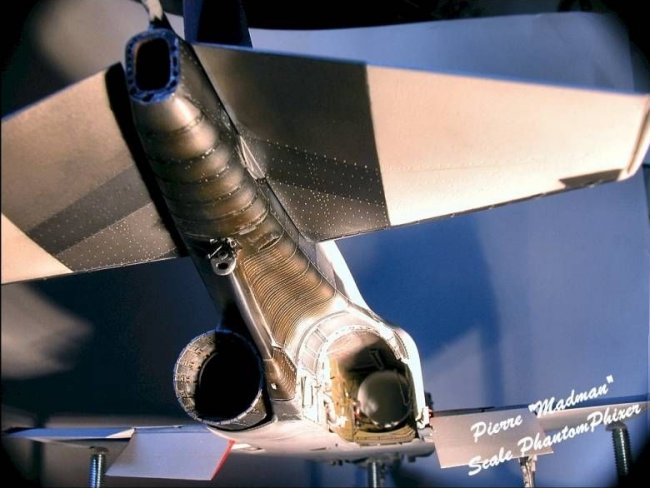
This is a close up of the area, detailing the vent and exhaust
fairing attached with tiny CA drops. Note the dark well behind the
blinds of the vent? It adds a pretty realistic look to the
model.
|
 |
|
A "Before
- After" picture says it better than many
words. |
|
Here is the final result,
after a heavy painting and weathering session of the exhaust blast shields and
arrestor hook. Looking at this picture, a former Phantom Phixer said "... it
reminds me when I used to work on the birds. I can picture me pounding rivets in
the engine bay..."
Someone else mentioned:
" I didn't know they had an F-4S on display in Switzerland. Now how about a
photo of your model?"
These kind of comments
make my day :-)
Happy modeling!
Pierre
"Madman"
Scale
PhantomPhixer
|
|